Function similar to Document Scanner. Given images of A4 paper sheets, output paper sheets’ four corners as well as four edges and their equations. Then crop the background and leave the paper sheet in proper position and standard scaling. We can do this in three steps. Firstly, detect edges with hough transform. Then store the corners in order. Lastly, applying a perspective transform to warp the image.
Here’s a Document Scanner tutorial implemented with OpenCV(without all theory details).
Edge Detection with Hough Transform
★Here’s an excellent c++ example part of the CImg Library project: Computation of the Hough Transform Illustrate the computation of the Hough transform to detect lines in 2D images. Provide also simple user interface to select and display lines
Theory
The purpose of the Hough transform is to address this problem by making it possible to perform groupings of edge points into object candidates by performing an explicit voting procedure over a set of parameterized image objects (Shapiro and Stockman, 304).
Reference: wiki
The Hough transform is a feature extraction technique. The simplest case of Hough transform is detecting straight lines. In general, the straight line $y = mx + b$ can be represented as a point $(b, m)$ in the parameter space. However, vertical lines pose a problem. They would give rise to unbounded values of the slope parameter m. Thus, for computational reasons, Duda and Hart[5] proposed the use of the Hesse normal form
$$rho = x\cos \theta + y\sin \theta$$
where $r$ is the distance from the origin to the closest point on the straight line, and $\theta$ is the angle between the $x$ axis and the line connecting the origin with that closest point.
Even if lines are not vertical, parameter $m$ and $b$ can get rather large which is hard to define their bounds. The transform is necessary.
It is therefore possible to associate with each line of the image a pair $(r,\theta )$. The $(r,\theta )$ plane is sometimes referred to as Hough space for the set of straight lines in two dimensions.
Given a single point in the plane, then the set of all straight lines going through that point corresponds to a sinusoidal curve in the $(r,\theta )$ plane, which is unique to that point. A set of two or more points that form a straight line will produce sinusoids which cross at the $(r,\theta )$ for that line. Thus, the problem of detecting collinear points can be converted to the problem of finding concurrent curves.
Also see: MathWorks: hough.
Implementation
Note: the codes has been updated (improved) in GitHub.
Reference: Leo’s blog
Init
The hough_space is a parameter space matrix whose columns and rows correspond to $angle$ and $rho$ values respectively. Its width range represents the possible degrees of each angle of the straight line passing through a point. Its height range represents the largest possible of $rho$ which is the distance of two diagonal corners in image.
|
|
Pre-treatment
- Convert rgb image to grayscale image because the color information helps little here.
- Blur the grayscale image helps a lot in noise reduction and focusing on the real edges.
- Get intensity gradient magnitude of grayscale image for edge detection. For each pixel in grayscale image, it’s intensity gradient magnitude is calculated by $\sqrt{gradX^2 + gradY^2}$. I use one dimensional filter (next pixel value minus previous pixel value in x-axis and y-axis for $gradX$ and $gradY$ respectively).
|
|
|
|
CImg function usage: Using Image LoopsCImg_3x3(I,type) : Define a 3x3 neighborhood named I, of type type. Actually, I is a generic name for the neighborhood. In fact, these macros declare a set of new variables.
For instance, defining a 3x3 neighborhood CImg_3x3(I,float) declares 9 different float variables Ipp,Icp,Inp,Ipc,Icc,Inc,Ipn,Icn,Inn which correspond to each pixel value of a 3x3 neighborhood. Variable indices are p,c or n, and stand respectively for ‘previous’, ‘current’ and ‘next’. First indice denotes the x-axis, second indice denotes the y-axis. Then, the names of the variables are directly related to the position of the corresponding pixels in the neighborhood.
Ipp = img(x-1,y-1)Icn = img(x,y+1)Inp = img(x+1,y-1)
cimg_for3x3x3(img,x,y,z,c,I,T) : Loop along the (x,y,z)-axes using a centered 3x3x3 neighborhood.
Transform to Hough Space
The elements in the hough_space represent accumulator cells. Initially, the value in each cell is zero. Then, for each pixel at $(x,y)$ with strong gradient (larger than GRAD_THRESHOLD), $rho$ is calculated for every $angle$ between 0 and 360 degrees, and $rho$ is calculated for every $theta$. $rho$ is rounded off to the nearest allowed row in hough_space.
If $rho$ is valid, we look for the accumulator’s bin that the parameters $(angle,rho)$ fall into, and increment the value of that bin.
At the end of this procedure, a value of $Q$ in hough_space(a, r) means that $Q$ points in the xy-plane lie on the line specified by $angle(a)$ and $rho(r)$. Peak values in the hough_space represent potential lines in the input image.
|
|
Looking for Local Maxima in Hough Space
By finding the bins with the highest values, typically by looking for local maxima in the accumulator space, the most likely lines can be extracted, and their (approximate) geometric definitions read off. (Shapiro and Stockman, 304)
In order to find these peaks, I apply threshold of the form (modify from this paper)
$$floor(maxVal/Q)$$
maxVal is the max value in the accumulator space hough_space, Q is used to adjust threshold. In the paper, $Q=\sqrt 2$, but I set $Q=3$ in my code so that more than three local maxima can be filtered out in all test images. It’s fine that more than 4 local maxima are filtered out because we can easily pick the four brighest(largest pixel value) points which correspond to four edges of a paper sheet.
By setting value in hough_space smaller than threshold to zero(black) we can clearly see how many local maxima are filtered out.
By the way, a good form of threshold saves you from adjusting parameters for each image.
|
|
Find Lines
Transform points in hough space to lines in parameter space.
$$m=-\frac {\cos \theta}{\sin \theta}$$
$$b=-\frac {rho}{\sin \theta}$$
Notice the case of line perpendicular to x axis:
$$x=rho$$
|
|
Find Corners
Since the lines returned do not contain any length information, we have to find the end points of each line by calculating the intersections (the corners too) of two lines. Normally,
$$
\begin{cases}
y=m0x+b0 \\
y=m1x+b1
\end{cases}
$$
=>
$$
\begin{cases}
x=\frac{b1-b0}{m0-m1} \\
y==m0*x+b0=m1*x+b1=(m0*x+b0+m1*x+b1)/2
\end{cases}
$$
Also take vertical lines into consideration in the following code.
The following code is a little redundant which calculates each intersection point twice and have to average two version of y for the identical value. Cleaner and neater code are welcome to share!
|
|
Display Corners and Lines
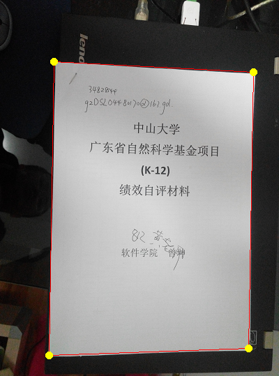
Lastly, draw and print corners and lines in original rgb image.
|
|
A Typical Example
From left to right, images of first row are the rgb_img, gray_img.blur(BLUR_SIGMA) and gradients; images of second row are hough_space after houghTransform(), hough_space after getHoughEdges() and rgb_img with detected lines and corners respectively.

- We can see that process of blurring weaks the handwriting and edge of table a lot.
- Contour of paper sheet is extracted after
getGradient(). - Performing
houghTransform(), we get a beautiful Hough space graph which is stored in matrixhough_space. Its cell value represents the number of curves through any point. Higher cell values are rendered brighter. The four distinctly bright spots are the Hough parameters of the four lines. - In
getHoughEdges()function, we extract them by applying threshold. - From these spots’ positions,
angleand distance from image center(rho) of the four lines in the input image can be determined. Then four lines of the form $y=mx+b$ and their intersections can be determined. Here’s the output indicating line equations and corner coordinates.
|
|
Image Warping and Perspective Transform of 2D Image
Theory
Reference
Paper(in chinese): Perspective Image Rectification Based on Improved Hough Transformation and Perspective Transformation
Image Warping Slides by Thomas Funkhouser.
CVPR Slides by Kun Zeng, SYSU.
Futher reading: 2D Image Morphing Algorithms
Concepts
Image filtering: change range of image.
Image warping: change domain of image. Manipulating pixel positions.
Source Image: Image to be used as the reference. The geometry of this image is no changed.
Target Image: this image is obtained by transforming the reference image.
(x,y): coordinates of points in the reference image
(u,v): coordinates of points in the target image
f,g or F,G: x and y component of a transformation function
Control points: Unique points in the reference and target images. The coordinates of corresponding control points in images are used to determine a transformation function.
A Transformation Function: used to compute the corresponding points
Perspective/Projective Transform: Allow a square to be distorted into any quadrilateral. Inverse is also projective. Good when controlling a warp with quadrilaterals, since 4 points in 2D determine the 8 degrees of freedom.
Perspective Transform Parameters Calculation
After obtaining four edges and corners of paper sheet, the next step is mapping. A transformation describes the destination (u,v) for every location (x,y) in the source in this case (quadrilateral->quadrilateral) is perspective transform.
$$u=\frac{ax+by+c}{mx+ly+1}, v=\frac{dx+ey+f}{mx+ly+1}$$
The above equations can also be rewritten as:
$$\begin{bmatrix}u\\v\\ \end{bmatrix} = \begin{bmatrix}x&y&1&0&0&0&-ux&-uy\\0&0&0&x&y&1&-vx&-vy\\ \end{bmatrix} \begin{bmatrix}a\\b\\c\\d\\e\\f\\m\\l\\ \end{bmatrix}$$
In which $a$, $b$, $x$, $d$, $e$, $f$, $m$, $l$ are parameters of perspective transform. Eight equations are need to find out these eight parameters. Mapping four corners(control points) $(x_1,y_1)$, $(x_2,y_2)$, $(x_3,y_3)$, $(x_4,y_4)$ in source image to $(u_1,v_1)$, $(u_2,v_2)$, $(u_3,v_3)$, $(u_4,v_4)$ in destination image with perspective transform, we get
$$\begin{bmatrix}
u_1\\v_1\\u_2\\v_2\\u_3\\v_3\\u_4\\v_4\\ \end{bmatrix} =
\begin{bmatrix}x_1&y_1&1&0&0&0&-u_1x_1&-u_1y_1\\0&0&0&x_1&y_1&1&-v_1x_1&-v_1y_1\\x_2&y_2&1&0&0&0&-u_2x_2&-u_2y_2\\0&0&0&x_2&y_2&2&-v_2x_2&-v_2y_2\\x_3&y_3&3&0&0&0&-u_3x_3&-u_3y_3\\0&0&0&x_3&y_3&1&-v_3x_3&-v_3y_3\\x_4&y_4&4&0&0&0&-u_4x_4&-u_4y_4\\0&0&0&x_4&y_4&1&-v_4x_4&-v_4y_4\\ \end{bmatrix}
\begin{bmatrix}a\\b\\c\\d\\e\\f\\m\\l\\
\end{bmatrix}$$
Or
$$UV=A\times M$$
Eight parameter in matrix form can be calculated by
$$M=A^{-1}\times UV$$
Reverse Mapping
Forward Mapping(Bad): Iterate over source image, sending pixels to destination. With this method, many source pixels can map to same destination pixel and some destination pixels may not be covered.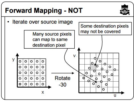
Inverse Mapping(Better): Iterate over destination image, finding pixels from source. (x,y) does not usually have integer coordinates. Must resample source. May oversample, but much simpler! Pseudo-code:
|
|
Here the F, G is the inverse transform of $u=\frac{ax+by+c}{mx+ly+1}, v=\frac{dx+ey+f}{mx+ly+1}$. Solve it and get
$$\begin{cases}
x=F(u,v)=\frac{(c-u)(vl-e)-(f-v)(ul-b)}{(um-a)(vl-e)-(vm-d)(ul-b)} \\[2ex]
y=G(u,v)=\frac{(c-u)(vm-d)-(f-v)(um-a)}{(ul-b)(vm-d)-(vl-e)(um-a)} \\[2ex]
\end{cases}$$
Point Sampling with Bilinear Filter: weighted sum of four neighboring pixels.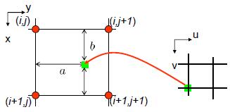
$$Img_{dest}(x,y)=(1-a)(1-b)Img_{src}(i,j) + a(1-b)Img_{src}(i+1,j) + (1-a)b Img_{src}(i,j+1) + (1-a)(1-b)Img_{src}(i+1,j+1)$$
Implementation
Note: the codes has been updated (improved) in GitHub.
Environment
C++ language.
Matrix operations implemented with Eigen (a C++ template library for linear algebra: matrices, vectors, numerical solvers, and related algorithms).
Using Eigen with Microsoft Visual Studio: download (e.g. Eigen 3.3.3), unpack in EIGENDIR (e.g. F:\eigen3.3.3), add EIGENDIR in VS Project(Project->Properties->C/C++->General->Additional Include Directories->F:\eigen3.3.3;), include header file (e.g. #include<Eigen/Dense>), use(e.g. Eigen::MatrixXf UV(8, 1);).
Image processing operations implemented with The CImg Library.
Usage: download CImg.h file, include by include "CImg.h"
Codes
- Step1: Before mapping, we need to get four control points in source image and destination image respectively. Destination corners can be easily defined
|
|
Source corners need to be in the same order as destination corners so as to map one by one correctly. The following method is a bit tricky and may not apply to all situations but for most of cases it works well.
|
|
- Step2: calculate perspective transform parameters
|
|
- Step3: reverse mapping
|
|
- Auxiliary function
|
|
Results
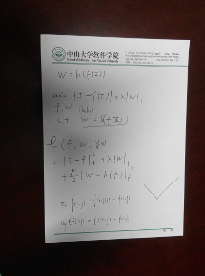
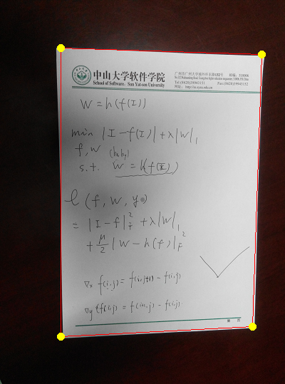
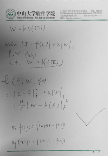
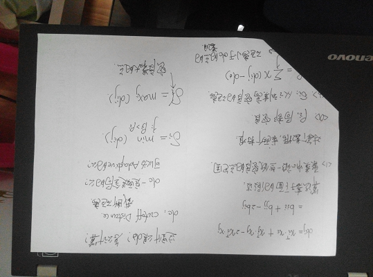
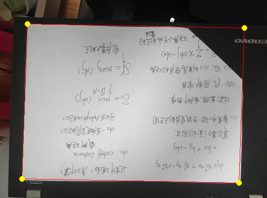
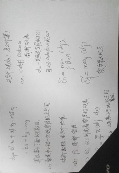
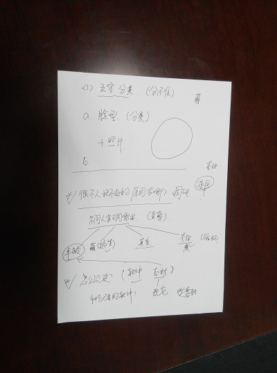
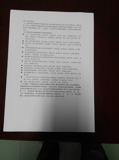
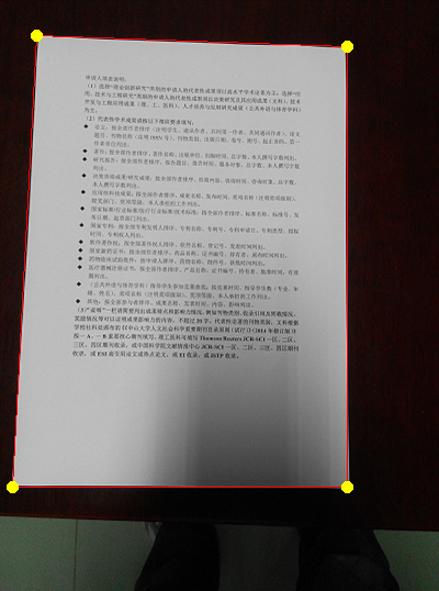
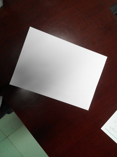
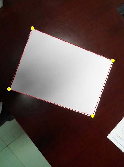
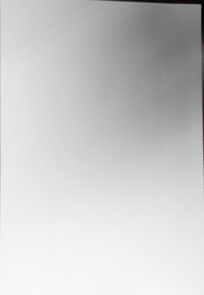
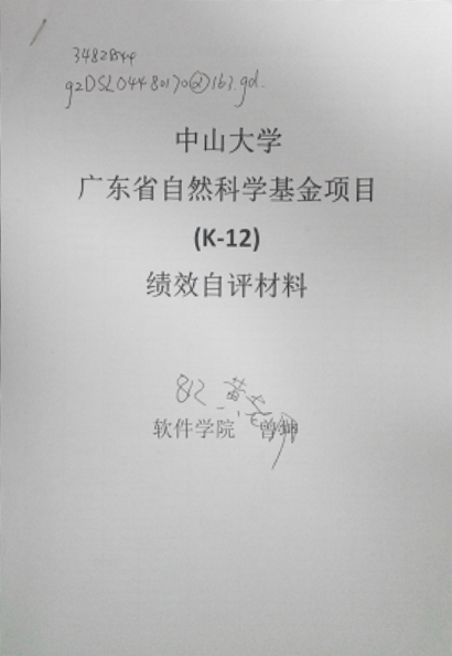
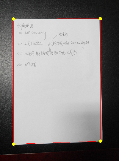
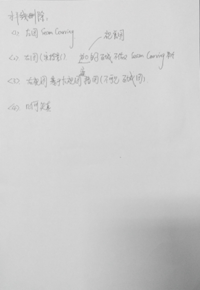
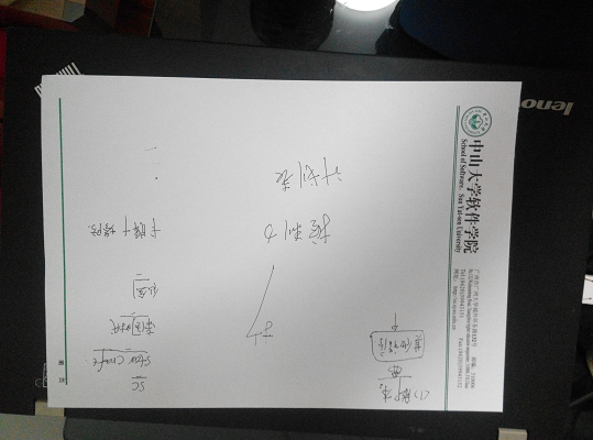
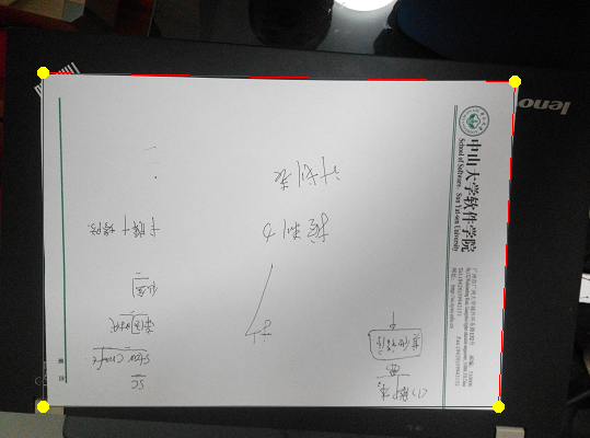
All source images have resized to around 400px*539px, 631KB to save space and process time.
Following are original image, image with mark of edges and corners and cropped image respectively each row.

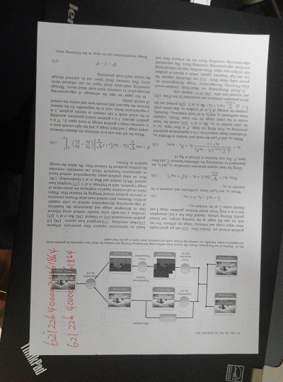
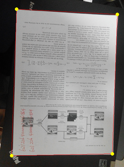
Pros and Cons
Pros: Most of the lines and corners are detected correctly in different circumstances(background, angle, noise, handwriting, light, shadow, imcomple paper sheet etc.) without tuning parameters for each image seperately.
Cons: Cropped results is blureed due to bilinear interpolation. A few of the lines and corners are not aligned perfectly. There are several reasons:
- “Due to imperfection errors in the edge detection step, there will usually be errors in the accumulator space, which may make it non-trivial to find the appropriate peaks, and thus the appropriate lines.”
- High-precision type like
doubleis used for parameters likemandbwhile some parameters likeangle,rhoand cordinates of points have to use type likeintfor pixel by pixel calculation and storage in matrix. Error is produced when casting type. - The edges in images are not straight.