Produce a “morph” animation of one image into another image, which involves two parts: cross dissolving and affine warping.
Approaches
GOAL
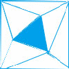
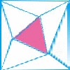
Morph a blue triangle tri1 to a pink triangle tri2 according to their three vertices respectively.

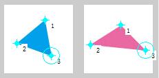

Left: tri1; Middle: corresponding vertices of tri1 and tri2; Right: tri2
The ideal transition is as follow.

Left: tri1 morph to tri2; Middle: tri1 morph to tri2 slowly in 5 frames; Right: each frame of slow transition
Process
Firstly, slice two images into triangles in the same way. Four corners of images are appended so as to cover entire image with triangles.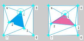
Then, warp tri1 from shape of tri1 to shape of tri2 for each triangle respectively. Do the same for tri2 (warp tri2 from shape of tri1 to shape of tri2).
Lastly, perform cross-dissolve of two warp’s colors.

Left: warp of tri1; Middle: warp of tri2; Right: cross-dissolve of two warp’s color
Details
Morphing is defined as the animated transformation of one image into another. We do it by producing sequence of frames. As shown above, morphing involves two parts: cross dissolving and warping.
Cross dissolving is linear interpolation to fade from one image to another. In another word, interpolate a value from 0 to 1 and use $A*value + B*(1-value)$ as the frame value.![]()
Simply using cross-dissolving will cause double-exposure effect in misaligned regions. So we need to align the two images before cross dissolving
Warping is used for this purpose. Pixels are “moving” from frame to frame in this process. A mapping rule is used to determine the way in which the pixels in one image should be mapped to the pixels in the other image.
Here I use affine transformation for warping triangles. Given two triangles ABC and A’B’C’ in 2D, the transformation matrix to transfer all pixels from one to the other is
$$
\begin{bmatrix}x’ \cr y’ \cr 1 \cr \end{bmatrix} =
\begin{bmatrix}a & b & c \cr d & e & f \cr 0 & 0 & 1 \cr \end{bmatrix}
\begin{bmatrix}x \cr y \cr 1 \cr \end{bmatrix}
$$
a,b,c,d,e,f are constants and x’, y’, x, y are 1-by-3 vectors. (e.g. $x=[x_A,x_B,x_C]$).
Write the formula in short: $p’=Ap$.
In this way, two images are sliced into triangles one-to-one. The one-to-one relationship between pair of triangle in two images is fixed for smoothly transformation. That is to say, triangle#n of frame t is always mapped to triangle#n of frame t+1.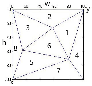
Each pair of triangle has a transformation matrix for mapping. This matrix will change from frame to frame since the shape and position of triangles will change from frame to frame.
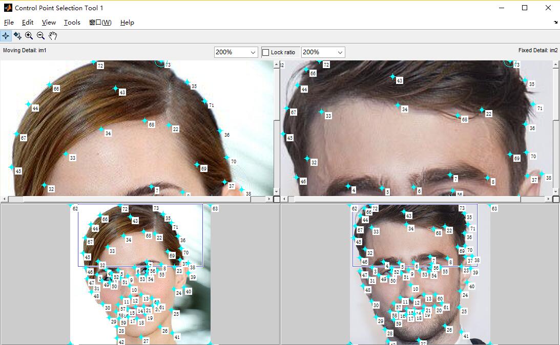
Now the problem is how to compute $A$. Since $p$ is a $3\times 3$ square matrix, it is invertible. $A=p’p^{-1}$. Points $p’$ and $p$ are specified by six vertices in each pair of triangles. We call them control pixels/points, which usually specify prominant features in the images. Select points on features that we want to align during the morph in a consistent manner using the same ordering of all keypoints (the more points, the better the morph, generally): eyes, ears, nose, mouth, etc.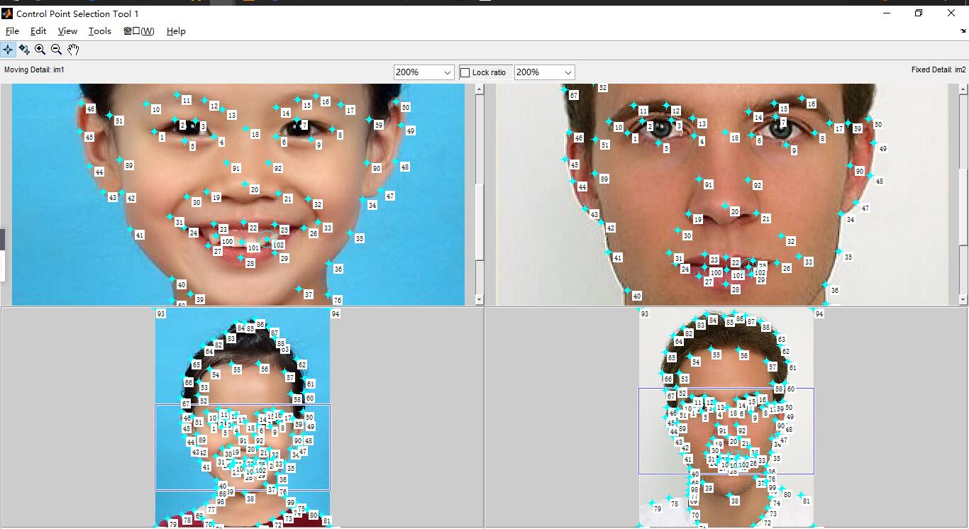
Having known $A$, the coordinate transform matrix, the non-marked points $p’$ (all pixels in triangles except vertices) can be computed from source points $p$. There are two ways to do this.
- Forward warping: send each pixel $p$ to its corresponding location $p’=Ap$ in the second image.
- Inverse warping: get each pixel $p’$ from its corresponding location $p=A^{-1}p’$ in the first image.
Inverse warping is a better way. See my discussion in A4 paper sheet detection and cropping for more details.
Implementation
Language: Matlab.
Attention: Hopefully my comments are detailed enough, I will not talk a lot in this part. The code below is an excerpt; full source is here.
The process is clear. Firstly, define correspondences and then produce each frame of the morph sequence specified by a fraction from 0 to 1.
|
|
Defining Correspondences
|
|
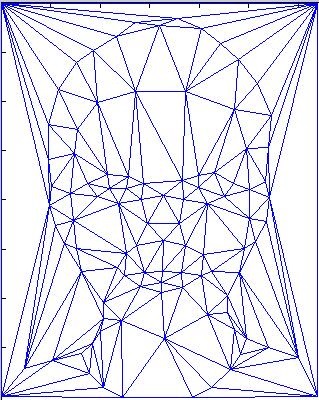
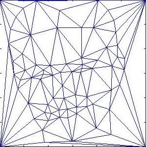
As I have mentioned, the one-to-one relationship between pair of triangle in two images is fixed. The triangulation is computed by the mean of the two point sets to lessen the potential triangle deformations. Each row of tri specifies a triangle defined by indices with respect to the points. In other word, tri is a matrix storing three vertices’s indexes of each triangle. The relative order of triangles will not change so we can tell which triangle from source image corresponds to which triangle in destination image.
The Morph Sequence
|
|
Affine warp
This part is a little tricky in implementation.
|
|
Results and Analysis
Image morphing can be applied to any object, but obviously it will have better effect for objects with similar structure and uniform background. Human faces set an example.
Human faces
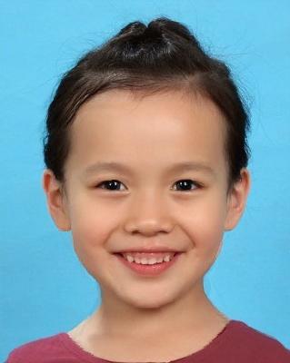
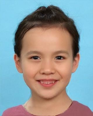
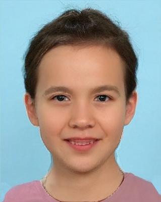
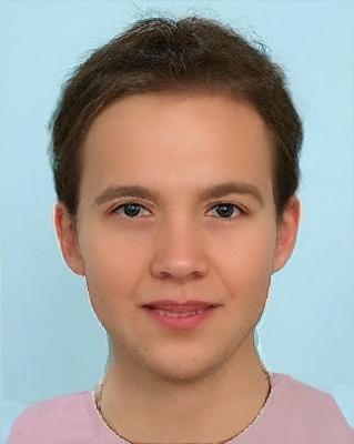
Girl Morph to Boy
For human faces, about 60 control points are enough. Here I use about 100 control points for fine-grained result. From the girl to the boy, there are 11 frames of animation between them where each frame is displayed for 0.1 second.
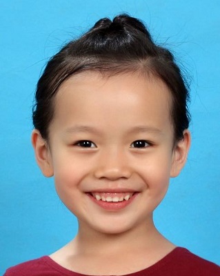
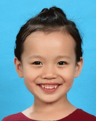
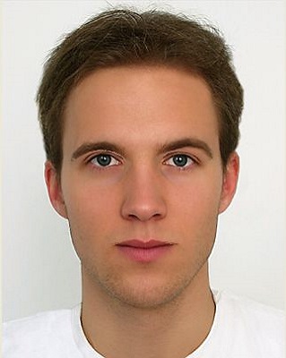
Here are the “mid-way” faces of frame 2, 4, 6, 8, 10. The fourth image is the triangulation of average face(frame 6)
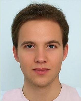
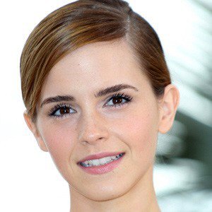
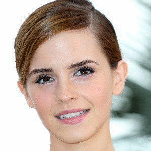
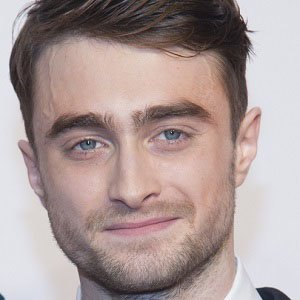
Watson Morph to Daniel
Can you tell whom this average face are combined of???
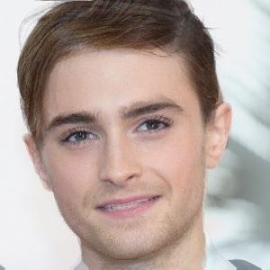
Emma Watson and Daniel Radcliffe!
The selection of control points for hair is tricky since one is round while the other is square. Anyway, just select a set of points you want to map.
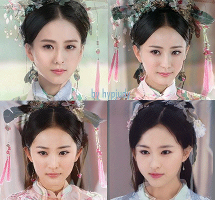
Average Face of Chinese Beauty
Game time! Take a guess.
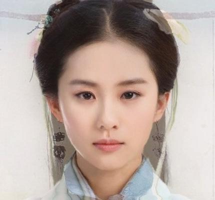
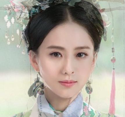
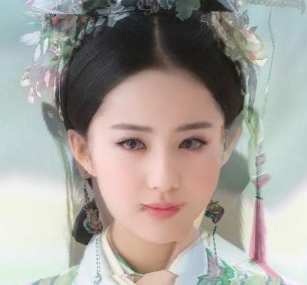
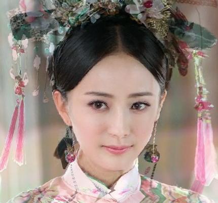
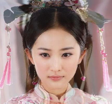
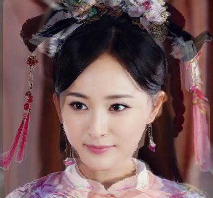
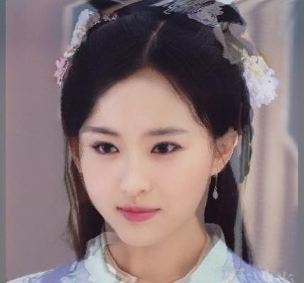
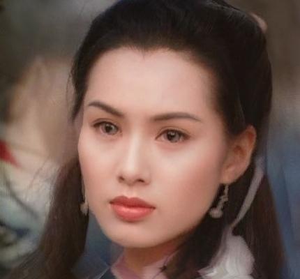
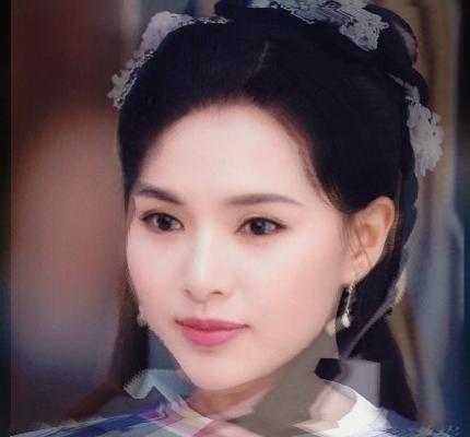
As you can seen, these “combined” beauties still have rather real and clear faces which perfectly combine their two “source” beauties’s features. But the backgrounds and headwears have double-exposure effect due to lacking corresponding aligned objects.
Peking Opera Mask Morphing
In fact, my original intention was to produce a morphing music video of the traditional Chinese Peking Opera masks! At first glance, its rather simple because all masks are oval, symmetrical, with mouth/eyes/nose/ears and without background. However, I gave up after morphing a pair of masks.
I used more than 100 control points and felt rather difficult to find corresponding control points. And this is the simplest one! Take a look at the following masks.
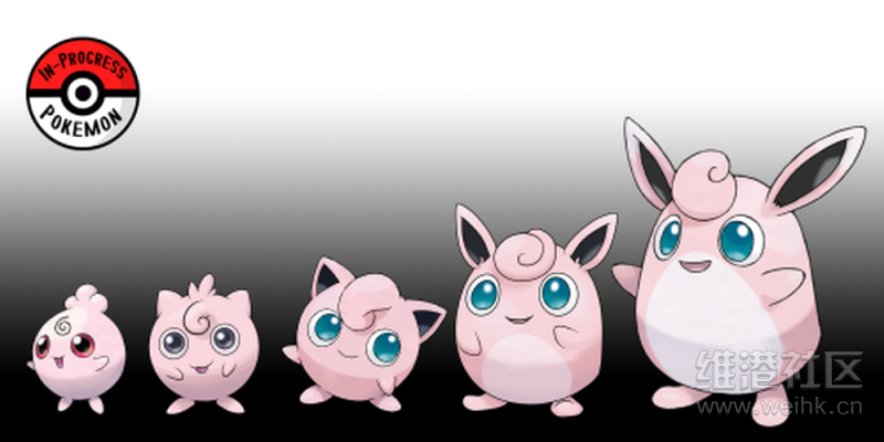
Cartoon Character Morphing
For fun, I morph a spirit in Pokemon GO. The effect is not very good due to the same reason. You can take it as a counter-example.
Future work
- C++ implementation with CImg and Dlib library (automatic morphing for faces).
- The “Mean face” of a population
- Caricatures: Extrapolating from the mean
- “visual lip-syncing”
- Other funny application…
Reference & Credits
All images (except the small blue and pink triangles) come from website. Thanks to them all.
- Face Morphing project of CSCI1950-g, Brown University.
- Face Morphing project of CS194-26, UC Berkeley.
- Courseware: Image Warping and Morphing of CS194-26, UC Berkeley.
- Courseware: Affine Transformations of CS384G, University of Texas at Austin.
- Reports of face morphing project of CS194-26, UC Berkeley. E.g. Report by Howard Nguyen, report by Rachel Albert and report by Nathaniel Mailoa.
- Python implementation by Rachel Albert.
- Matlab implementation by Harrison Wang.
- Composers Music Video by Nathaniel Mailoa.
- Image Morphing: A Comparative Study by Prashant K. Oswal and Prashanth Y. Govindaraju